Connectionless transport management for long-run sessions

Why does the connection between your device and server get intermittently disrupted? This can be quite frustrating, as lost connections reduce overall solution efficiency, in particular, decreasing battery lifespan and amplifying cloud connection costs. However, it is perfectly normal behaviour, with several potential causes, including the most likely one: the way Network Address Translation (NAT) works.
NAT typically maintains an internal table (called a ‘NAT table’) that maps a device’s internal internet protocol (IP) to the router’s external IP address. The NAT table is used to route responses from one side to the other.
Like all systems, devices are built on physical hardware, and hardware has limitations. Therefore, NAT tables cannot be infinite, which means they may struggle to maintain the mappings over a long period. The NAT timeout property exists to clear away stored mappings and help NAT effectively manage its Random Access Memory/Central Processing Unit (RAM/CPU) consumption. Referring to [RFC 4787 (chapter 4.3. Mapping Refresh)], this timeout is typically set to two minutes but can vary depending on the NAT implementation.
“NAT mapping timeout implementations vary, but include the timer’s value and the way the mapping timer is refreshed to keep the mapping alive.
The mapping timer is defined as the time a mapping will stay active without packets traversing the NAT. There is great variation in the values used by different NATs.
REQ-5: A NAT UDP mapping timer MUST NOT expire in less than two minutes, unless REQ-5a applies.”
If your device or server fails to send any packet during the timeout period, its corresponding entry in the NAT table will be marked for cleaning. This is why the link can be broken over time or after a long period of inactivity.
Now that the problem has been identified, how can we solve it? Let’s go over a few options in detail.
Raw UDP
User Datagram Protocol (UDP) is a connectionless protocol. Peers using this protocol do not maintain a continuous connection. In this sense, UDP can be considered a stateless protocol. In contrast, Transmission Control Protocol (TCP) is a connection-oriented protocol. Peers using this protocol maintain a connection between each other through various messages.
By default, UDP does not provide a mechanism to maintain a connection, but several methods for doing so exist. For instance, when sending Raw UDP (i.e., UDP packets that had nothing done to or added on top of it), a connection may be maintained by sending packets periodically, at least once every mapping timer interval (more or less, two minutes). This technique is called ‘keep-alive’ and can be seen as UDP packet ping-pong between the client and the server.
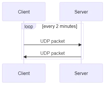
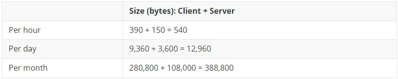
This method has a drawback: bandwidth consumption . Sending a packet every two minutes means an exchange of 30 packets per hour, 720 packets per day, 21,600 packets per month, and so on. The number of packets sent can grow very quickly and can become a problem for an application running on constrained networks.
Keeping sessions active in IoT
Let’s take a real-world example from the Internet of Things (IoT). IoT devices are constrained and rely on less-than-perfect networks. The latencies can be high while the throughputs are often low.
Given their connectionless nature, UDP packets can be lost or their delivery may be delayed. If a device sends a packet every two minutes, but the network drops one of these packets, the NAT table may close the connection. This happens frequently on constrained networks such as Long Range Wide Area Network (LoRaWAN), Sigfox, Narrowband-IoT (NB-IoT), and so on.
How is this problem handled by the well-known IoT protocol: the Lightweight Machine to Machine (LwM2M) protocol?
LwM2M provides a registration mechanism to maintain a shared context on an LwM2M Client and an LwM2M Server. The registration is based on the concept of lifetime, expressed in seconds.
The lifetime is a value sent by the LwM2M Client to the LwM2M Server, and it indicates how long the registration context is valid. To ensure the context remains active, the LwM2M Client must send a registration message to the LwM2M Server before the lifetime ends. If the LwM2M Client does not update its registration before the lifetime value runs out, the LwM2M Server will consider the LwM2M Client as deregistered. Otherwise, the lifetime timer resets every time the LwM2M Server receives a registration update message from the LwM2M Client.
To prevent raw UDP timeout problems, the lifetime value may be set lower than the NAT table timeout. However, this is not acceptable for the reason already explained earlier (i.e., excessive bandwidth consumption).
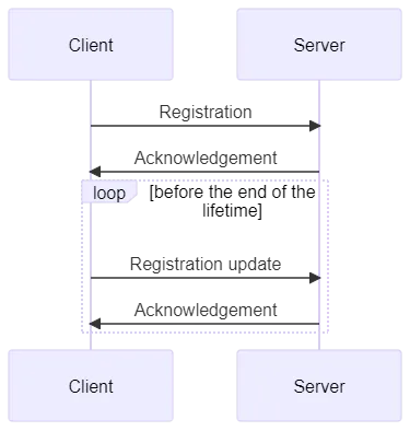
Here’s an example of real messages exchanged between an LwM2M Client and an LwM2M Server:
- The LwM2M Client sends a registration message to the LwM2M Server:
- POST /rd?ep=urn:imei:1234567890<=120&lwm2m=1.1&b=U
- Object lists: </1/0>;ver=1.1,</3/0>;ver=1.1,</5/0>,</3303/0>
- The LwM2M Server sends an acknowledgement message to the LwM2M Client:
- 2.01 Created
- Location-Path: </rd/1234>
- The LwM2M Client sends a registration update message to the LwM2M Server:
- PUT /rd/1234
- The LwM2M Server sends an acknowledgement message to the LwM2M Client:
- 2.04 Changed
We will not go into detail about this messaging sequence but focus on the cost of these exchanges in terms of bandwidth. If an LwM2M Client sends a registration update message every two minutes, and the LwM2M Server acknowledges the message, the total bandwidth cost for this interval is 18 bytes. The client will have sent 13 bytes, while the server will have sent five bytes.
Note: The first exchange is intentionally omitted, since it can be considered an ‘upfront cost’ and does not contribute to the maintenance of the connection in the long run.
What happens if the LwM2M Client does not send a registration update before the mapping on the NAT table expires? This happens when the lifetime value is longer than the NAT mapping timer; for instance, the lifetime is set to one hour, while the NAT mapping timeout is set to two minutes.
In this scenario, the LwM2M Client does not send a registration update before the NAT table expires, but the only real consequence is that the LwM2M Server cannot send any messages to the LwM2M Client after this event. The LwM2M Client must first send a registration message to the LwM2M Server to let the server associate the correct UDP peer with its LwM2M registration context. After that, the server will have two minutes (or whatever the value of the NAT mapping timer is) to send messages.
Apart from that, the LwM2M Client will not notice that much of an impact. If the NAT table mapping expires, the client can simply send a registration message to the server to resume communication between itself and the server.
UDP + DTLS
Datagram Transport Layer Security (DTLS) is a protocol based on UDP, provides the same security guarantees as TLS, and is defined in [RFC 9147]. Under the DTLS protocol, when a peer wants to establish an encrypted connection with another peer, they perform a handshake to negotiate security parameters.
The handshake is composed of the following messages. Note that this is not an exhaustive list because messages depend on the security parameters negotiated.
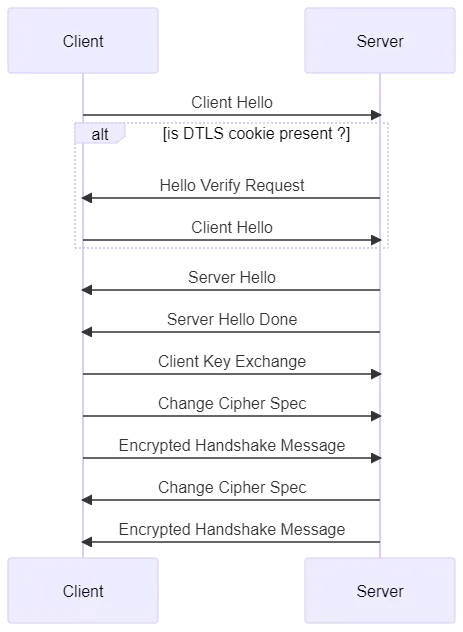
Once a DTLS session is established, the peers can send encrypted messages to each other. A session is closed when one of the peers sends a ‘Close Notify’ message.
The DTLS Server associates a DTLS Client through its IP address and port. It maintains a DTLS session for every DTLS Client, which means a client must always use the same IP address and port to communicate with a server. If the IP address or port changes, the DTLS server will be unable to associate the DTLS Client with its DTLS session.
When a DTLS Server receives a message from an unknown DTLS Client, it assumes that this message is a ‘Client Hello’. If this is not the case, the server will either drop the message silently or emit an alert message before closing the session.
Session resumption is one of the mechanisms used to renew a security session. It allows a client and server to establish a new secure session while reusing the security parameters negotiated and established in a previous session. This significantly reduces the overhead of establishing a new session, as it avoids the need for a full handshake. Under this mechanism, the client sends a session ID to the server. If the server recognises the session ID and is willing to reuse that session’s parameters, the session can resume:
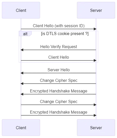
The handshake this time does not require the client to send a ‘Client Key Exchange’ message and the server to send a ‘Server Hello Done’ message.
The DTLS Client is responsible for initiating session resumption after a long period of inactivity (i.e., no communication between peers). The DTLS Server can’t trigger this mechanism, as it can only accept or reject incoming session resumption requests. However, the DTLS Client can re-establish a session with the DTLS Server only if the latter accepts the request.
The DTLS Client must use the session resumption mechanism to inform the DTLS Server of any changes to the IP address and/or port. It’s the only way to associate the correct IP address and port couple to the DTLS session for the server.
Resuming sessions in IoT
Using the earlier raw UDP example, you can see that nothing much changes for the LwM2M Client, except it must now initiate the session resumption mechanism before sending a registration update message. As usual, if no messages are sent within the timeout interval, the NAT table mapping will be cleaned, and the server will again be unable to send outbound messages to the client.
The only difference, this time, is that the client and server exchange more than 18 bytes (i.e., the registration update message and the acknowledgement of the message).
The client sends:
- Client Hello with Session ID (132 bytes)
- Client Hello with Session ID + Cookie (164 bytes): optional step
- Change Cipher Spec (14 bytes)
- Encrypted Handshake Message (53 bytes)
- Registration Update Message (13 bytes without encryption overhead)
=> Total of 363 bytes
The server conveys:
- Hello Verify Request (60 bytes): optional step
- Server Hello (111 bytes)
- Change Cipher Spec (14 bytes)
- Encrypted Handshake Message (53 bytes)
- Registration Update Message Acknowledgement (5 bytes without encryption overhead)
=> Total of 238 bytes
The total is 619 bytes, which is 363 + 238 + 18 (i.e., the bandwidth for the client’s registration update message and the server’s acknowledgement). This is 34 times more the size of the previous exchange.
For simplicity, we do not include encryption overhead in the above calculation, so we can expect the total size of exchange to be even bigger than indicated. Suffice it to say that obtaining a secure connection ‘costs’ more. This overhead is huge and can be a major problem for constrained networks.
Note: The example above is based on the Pre-Shared Key (PSK) cipher suite with the cipher suite: TLS_PSK_WITH_AES_128_CCM_8.
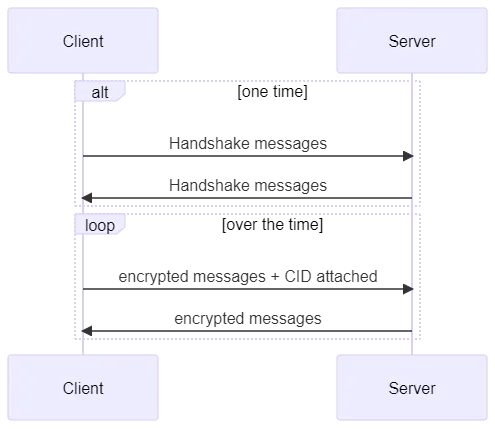
UDP + DTLS + Connection Identifier
How can we reduce the overhead of the session resumption mechanism under the DTLS protocol? The answer is the Connection Identifier (CID), which has been proposed in [RFC 9146] as an extension to the DTLS 1.2 protocol before being fully integrated into the DTLS 1.3 protocol.
The Connection Identifier, which is at most 32 bytes, is a value that identifies a DTLS session. It is generated by the DTLS Server and sent to the DTLS Client during the handshake. The DTLS Server then uses it to associate the DTLS session.
The Connection Identifier is sent clear, not encrypted, and is part of the DTLS record layer. Essentially, the DTLS Client must attach this value to every encrypted message it sends to the server.
Extract from the RFC 9146:
struct {
ContentType outer_type = tls12_cid;
ProtocolVersion version;
uint16 epoch;
uint48 sequence_number;
opaque cid[cid_length]; // New field
uint16 length; // New field
opaque enc_content[DTLSCiphertext.length];
} DTLSCiphertext;
The extension is negotiated during the handshake and is first exposed by the DTLS Client in the ‘Client Hello’ message. If the DTLS Server supports the extension, it will reply with the ‘Server Hello’ message + the Connection Identifier value. If one of the parties does not support the extension, the DTLS session will be established without the Connection Identifier.
The Connection Identifier eliminates the need for session resumption mechanisms since it enables the decoupling of the DTLS session from the IP address and port. The DTLS Client can change its IP address and port, and the DTLS Server will still be able to associate the DTLS session with the DTLS Client.
The DTLS Client simply has to attach the CID to every encrypted message, and the association will succeed, as long as the DTLS session is not interrupted by a ‘Close Notify’ message.
By eliminating the need for the costly session resumption mechanism, CID significantly reduces overhead.
CID in IoT
This workflow mimics the behaviour of Raw UDP but without the cost of a session resumption mechanism. The DTLS overhead remains, but that is deemed an acceptable cost because message encryption is a critical function. Due to cybersecurity considerations, sending unencrypted messages over the wire is out of the question for major IoT use cases.
The addition of the Connection Identifier to every message sent by the DTLS Client to the DTLS Server is the only downside to this solution, as it leads to encrypted messages that are a bit bigger than what they are in ‘regular’ DTLS. This is not a big deal, however, especially since common IoT use cases involve devices that are asleep most of the time and wake up only intermittently to send data to the server. What’s more important is that, compared to ‘regular’ DTLS, DTLS with a Connection Identifier reduces the number of messages exchanged and, thus, the overall number of bytes transmitted.
Note that, in this case, only the DTLS Client is required to attach the Connection Identifier to messages. The DTLS Server does not need to do it, so this solution does not incur any additional overhead server-side.
UDP + OSCORE
Trying to connect IoT devices to the cloud is akin to bridging two inherently incompatible worlds: IoT devices with their constraints and intermittent connectivity, and a virtually limitless cloud that is always-connected, with an IP-centric approach.
Earlier in this article, we outlined three different technical approaches for maintaining long running sessions between an IoT client and an IoT server. We left off at the DTLS + CID method, but is there a better strategy than using a Connection Identifier?
Potentially, there is. A new security mode has been proposed for the Constrained Application Protocol (CoAP) called Object Security for Constrained RESTful Environments (OSCORE). It is defined in [RFC 8613], and it is based on the CBOR Object Signing and Encryption (COSE) protocol defined in [RFC 9052 and RFC 9053]. CBOR stands for Concise Binary Object Representation, defined in [RFC 8949].
It is worth reiterating that this solution is specific to CoAP and can’t be used for other protocols. It is not a replacement for DTLS, but a new security mode that can be used on top of or with DTLS if necessary. That said, it can also be used without DTLS, i.e., OSCORE with UDP only.
We won’t go into too much detail, as we cover OSCORE in-depth in another article. For now, it’s important to understand that OSCORE enables the partial encryption of messages sent by a client to a server. This is how it can reduce overall encryption overhead and help save bandwidth.
How does the protocol help us solve the NAT table timeout problem?
How OSCORE remedies NAT table timeout in IoT
OSCORE is like a mixture of two solutions: ‘regular’ DTLS and the Connection Identifier extension.
Each security session is identified through a Key ID Context. This Key ID is used by a server to associate its internal security context with a client, pretty much the same way the Connection Identifier extension enables a server to associate a client with a particular session.
OSCORE also uses something similar to a DTLS handshake. However, the OSCORE handshake is much shorter. Moreover, since the messages exchanged between a client and a server are partially encrypted, the OSCORE ‘handshake’ overhead is much lower than that of the DTLS handshake.
To illustrate how OSCORE works in comparison to the UDP + DTLS + Connection Identifier solution, let’s go back to our LwM2M example from earlier.
To initiate a secure connection using OSCORE, the LwM2M Client sends its registration message during the negotiation of the OSCORE context with the LwM2M Server. The LwM2M Server replies with both the registration acknowledgement message and the end of the negotiation of the OSCORE context. There’s no need for the usual handshake messages in this case since they are directly part of the first application messages exchanged between the client and the server. The negotiation of the OSCORE context can also be derived multiple times through [RFC 8613 (Appendix B.2 Security Context Derived Multiple Times)].
Below is a comparison of the bandwidth needed to establish a secure connection using DTLS + CID and OSCORE:
DTLS (with cipher suite: TLS_PSK_WITH_AES_128_CCM_8) + Connection Identifier (with a length of 9 bytes): 988 bytes
- DTLS handshake: 746 bytes
Client Hello (137 bytes)
Hello Verify Request (60 bytes): optional step
Client Hello + Cookie (169 bytes): optional step
Server Hello (124 bytes)
Server Hello Done (25 bytes)
Client Key Exchange (41 bytes)
Change Cipher Spec (14 bytes)
Encrypted Handshake Message (69 bytes)
Change Cipher Spec (14 bytes)
Encrypted Handshake Message (93 bytes)
- LwM2M registration message: 242 bytes
Registration (165 bytes)
Acknowledgement (77 bytes)
OSCORE: 359 bytes
- OSCORE context negotiation with LwM2M registration message: 359 bytes
Registration (147 bytes)
Response with Appendix B.2 (28 bytes)
Registration with Appendix B.2 (157 bytes)
Acknowledgement (27 bytes)
Now, here is a comparison of the bandwidth the two solutions need to maintain a secure connection (looking only at the registration update and acknowledgement messages):
DTLS + Connection Identifier: 130 bytes
- LwM2M registration update message: 130 bytes
Registration Update (53 bytes)
Acknowledgement (77 bytes)
OSCORE: 65 bytes
- LwM2M registration update message: 65 bytes
Registration Update (48 bytes)
Acknowledgement (17 bytes)
Making OSCORE work for your IoT deployment
The NAT table timeout is not a simple problem to resolve, but there are ways to overcome it. Your choice of solution depends on your use case and the constraints of your particular application.
It is clear from the above discussion that OSCORE is one of the most efficient strategies for establishing and maintaining secure connections. Its workflows consume significantly less bandwidth than alternatives, so why is it not as widely used or as popular as DTLS + CID?
The lack of support for this security mode is hindering the widespread adoption of OSCORE in IoT. It didn’t help that, during the early days of its conceptualisation, some workflows were designed based on the incomplete OSCORE RFC, resulting in incompatible implementations.
The situation has greatly improved since the release of the final version of the proposed standard. However, the earlier confusion has done significant harm, contributing to OSCORE’s slower-than-expected uptake.
Now that there is a reliable basis for OSCORE implementations, it’s time to actively integrate OSCORE into IoT infrastructure, especially since we at Trasna offer a simple way to implement OSCORE end-to-end security for IoT.
Implementing OSCORE Through Alaska and Iowa SDK
To address NAT table timeouts using OSCORE, you need just two things: IoTerop Alaska and IoTerop Iowa.
IoTerop Alaska is an IoT device management platform, a single pane of glass from which you can launch and orchestrate connections for thousands or even millions of IoT devices. It gives you a unified interface or dashboard from which to monitor and manage IoT devices throughout their lifecycle, from commissioning, configuration, securing, updating, data collection to decommissioning.
Alaska makes true zero-touch commissioning possible and ensures IoT deployments are seamlessly scalable and effortlessly manageable. More importantly (and relevant to the current discussion about NAT table timeouts), it has support for both the popular DTLS protocol and the efficient OSCORE solution.
Managing your IoT network on Alaska means you can implement the OSCORE approach towards minimising long-run session disruptions between your IoT devices and your server, all while securing connections and reducing bandwidth consumption.
Alaska is an LwM2M server, so this gives rise to the question: How can you use Alaska to manage all types of IoT devices, even those without native LwM2M support? The answer is simple: Use the Iowa Software Development Kit (SDK).
Iowa SDK simplifies and accelerates IoT device deployment and management because it eliminates the need to build firmware from scratch. Install it on an IoT client to transform it to an LwM2M-capable device that can directly ‘communicate’ with your Alaska IoT device management platform. Activate the readily available OSCORE security protocol stack, and enable end-to-end encryption and the OSCORE solution to maintaining efficient and disruption-free connections.
How about existing, already deployed IoT devices that do not have native support for LwM2M? It can’t be easy to reprogram them to enable LwM2M.
The solution, in this case, is to create gateway devices through the Iowa SDK LwM2M gateway feature. Gateway devices serve as intermediaries between non-LwM2M clients and an LwM2M server. They ‘talk’ to IoT devices then ‘convert’ messages before relaying them to Alaska, and vice-versa. A gateway device equipped with the Iowa gateway feature can facilitate the seamless flow of data between non-LwM2M IoT clients and an LwM2M server like Alaska.
Alaska and Iowa are perfect complements to each other. Using both together is the easiest way to enable OSCORE end-to-end encryption and, more importantly, maintain long-running sessions between your IoT devices and your server.
Trasna is a leading provider of IoT solutions for enterprises, original equipment manufacturers, smart cities, and mobile network operators. Talk to a Trasna technical consultant to learn how you can use Alaska and Iowa SDK to design robust and scalable IoT systems.

Details
The landscape of smart cities, utilities, security systems, and device manufacturing is rapidly evolving.